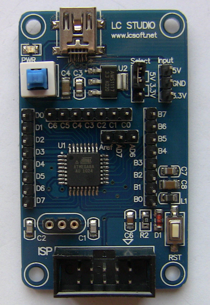
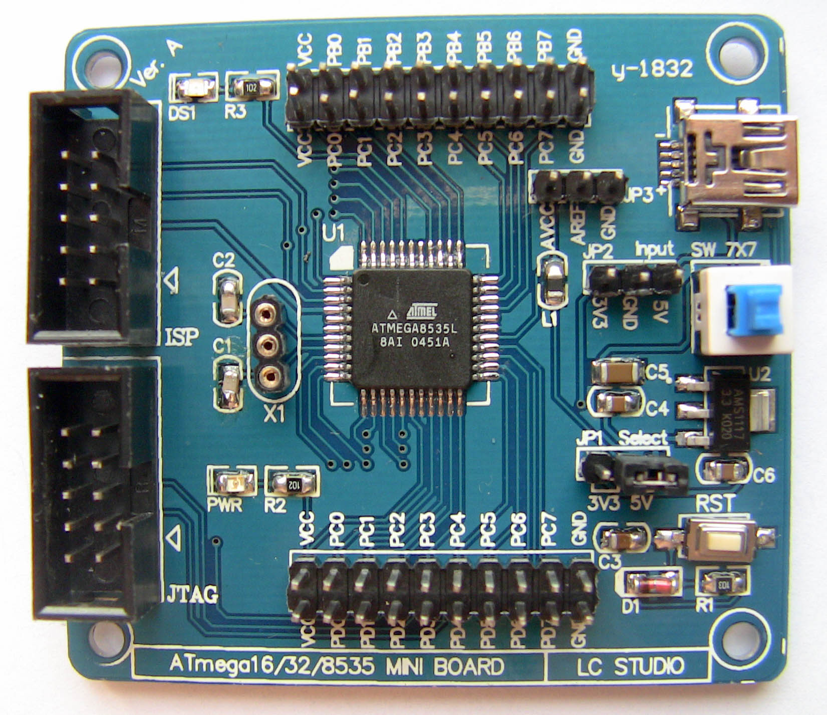
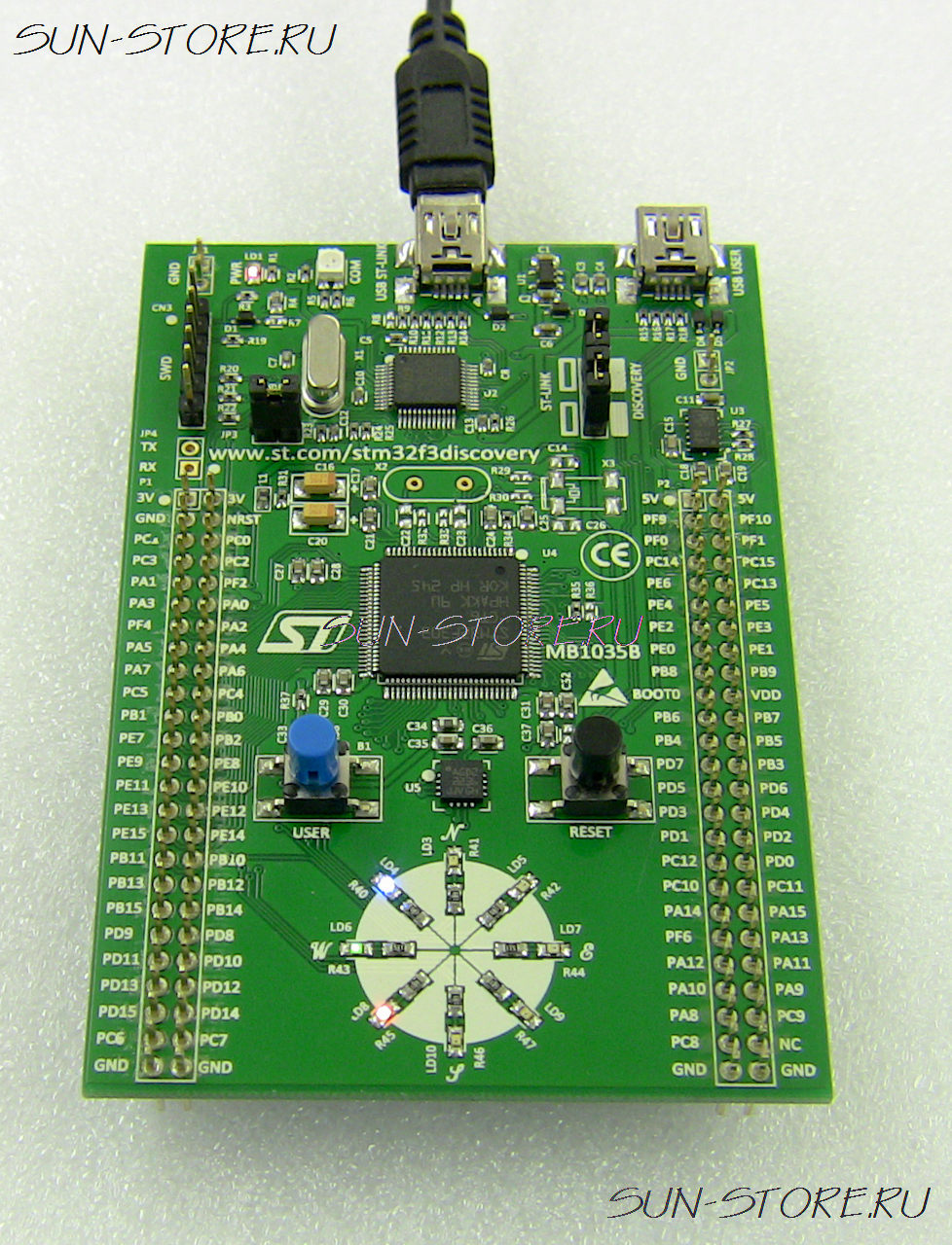
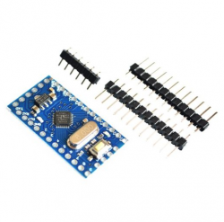
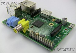
Модуль для разработки и отладки программ на чипе atmel 8 Мгц. Если вы читаете литературу микроконтроллеры avr вводный курс, то все примеры сможете воспроизвести на данной отладочной плата для avr. На плате имеются выводы для подключения внешнего кристалла, что позволит использовать вполне конкретную частоту, можно собрать очень точные часы atmega с использованием соответствующего кварца. Для подключения к этому микроконтроллеру atmega 8 программатора микроконтроллеров atmel достаточно только лишь соединить программатор и макетную плату кабелем, поставляемым в комплекте с программатором avr. Программатор и отладчик avr jtagice можно использовать с другими макетными платами на основе чипов Atmel, например avr atmega128 и многими другими, представленными в нашем магазине. Сам по себе avr kit является очень удобным практически в любой задаче. Благодаря переключателю напряжения питания, который позволяет установить напряжение для вашей схемы, можно испытать микроконтроллер фирмы atmel на низких частотах в условиях низкого энергопотребления. Так же бывает необходимо установить единое напряжение между стэкируемыми устройствами, ведь для большого числа электронных компонентов и модулей напряжение в 3.3 Вольта так же широко используется наравне с 5 Вольтами, переключить напряжение можно переставив один джампер. На плате так же присутствует кнопка сброса (RESET), которая позволяет сбрасывать программу без передергивания питания, что очень сильно упрощает жизнь, поверьте :). Для включения питания контроллера atmega используется кнопка, можно выключить питание и без опаски работать с выводами. Наличие питания индицируется светодиодом. Питание может быть подаваться через miniUSB порт, через разъем avr isp программатора или через специально выведенные пины (3.3V, 5V, GND). Если в задаче стоит использование atmega ацп, то будут очень полезны выводы для эталонного напряжения - Aref. Это прекрасный вариант для начинающих изучать микросхемы atmega, достаточно докупить программатор avr isp и вы сможете сразу же приступить к программированию.
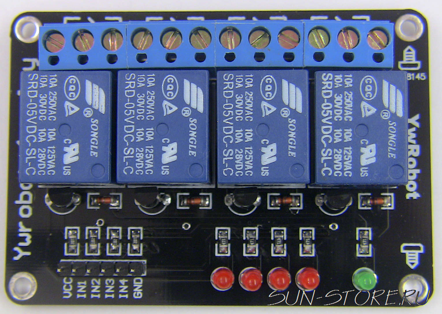
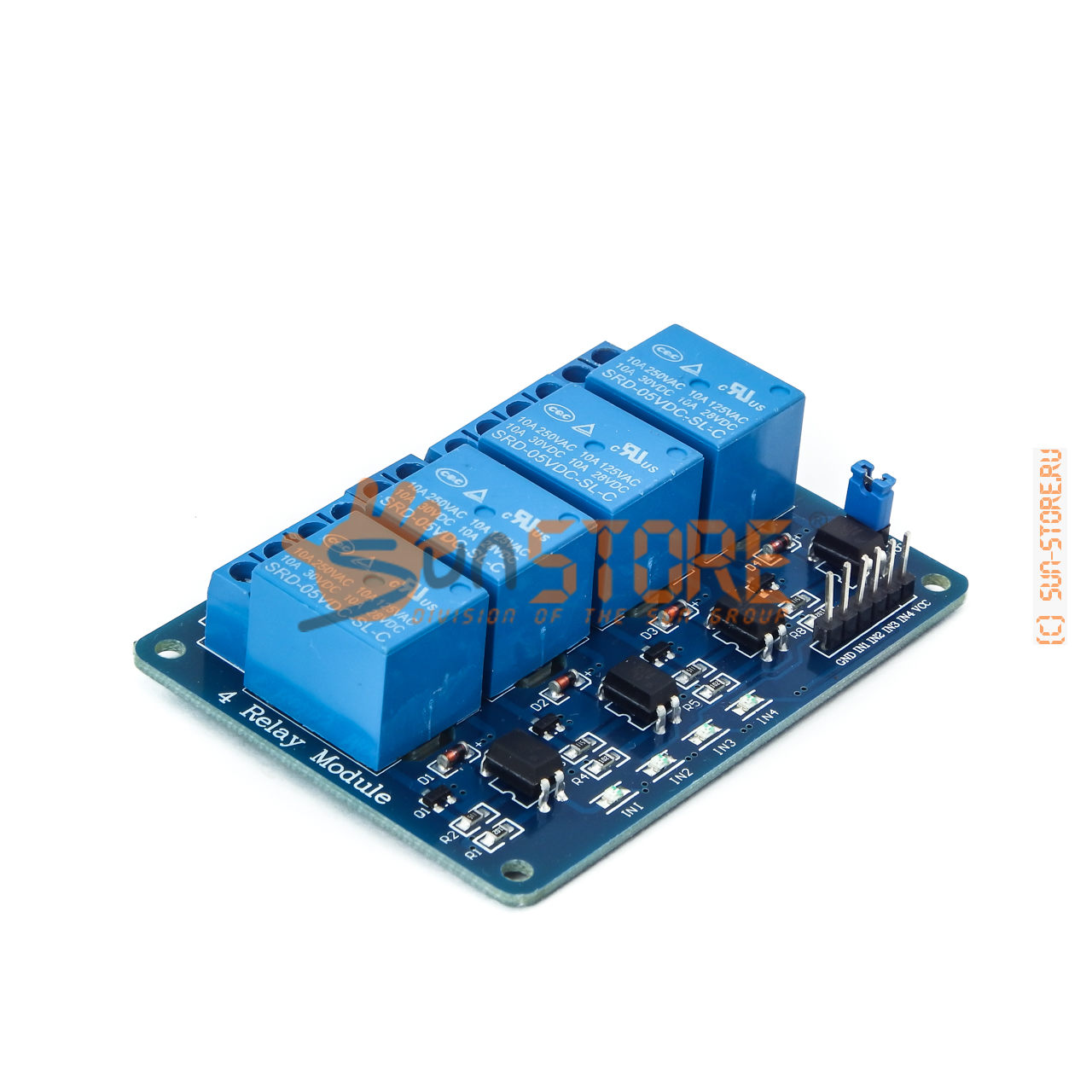
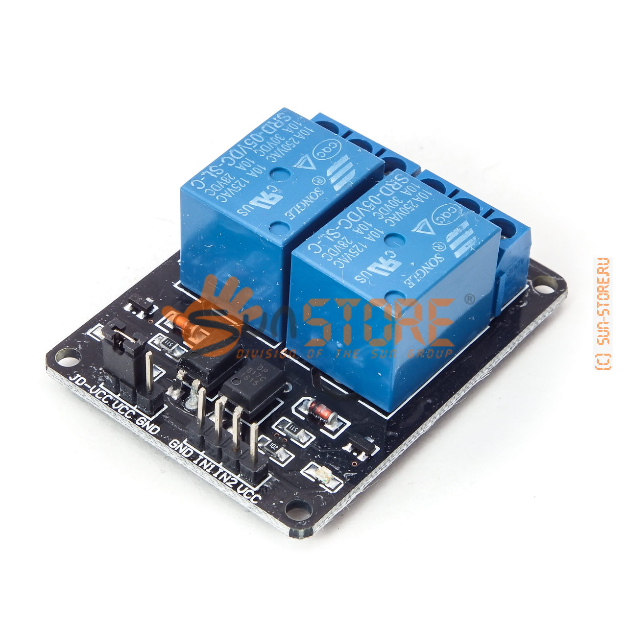
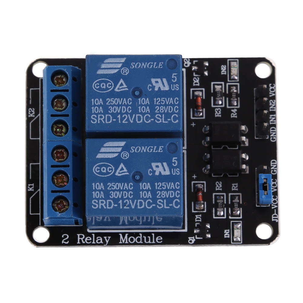
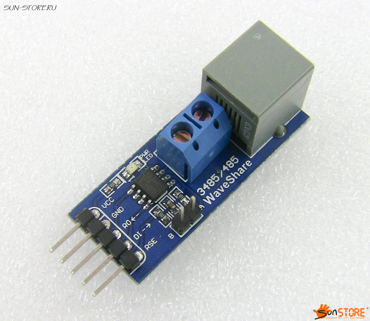
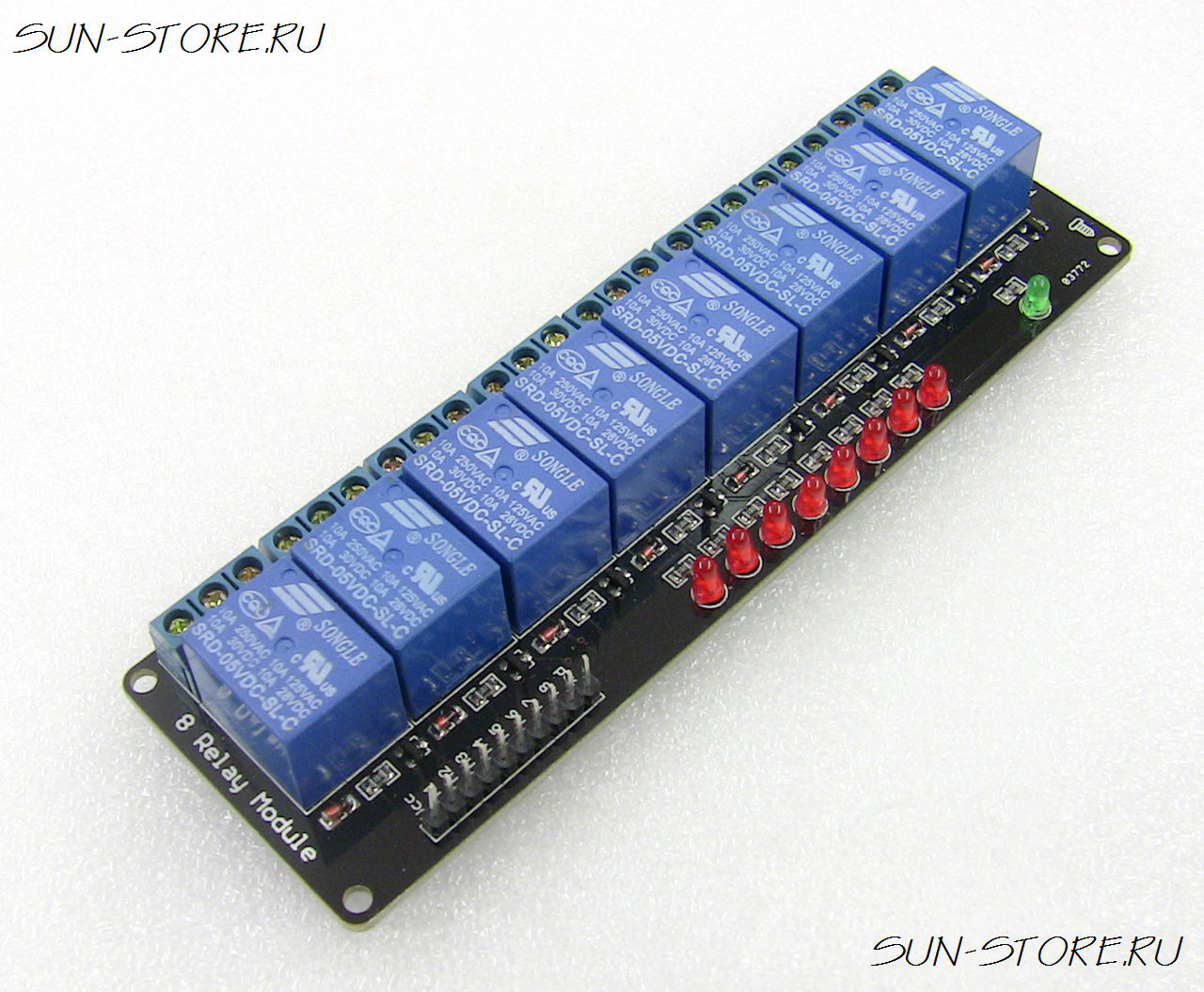
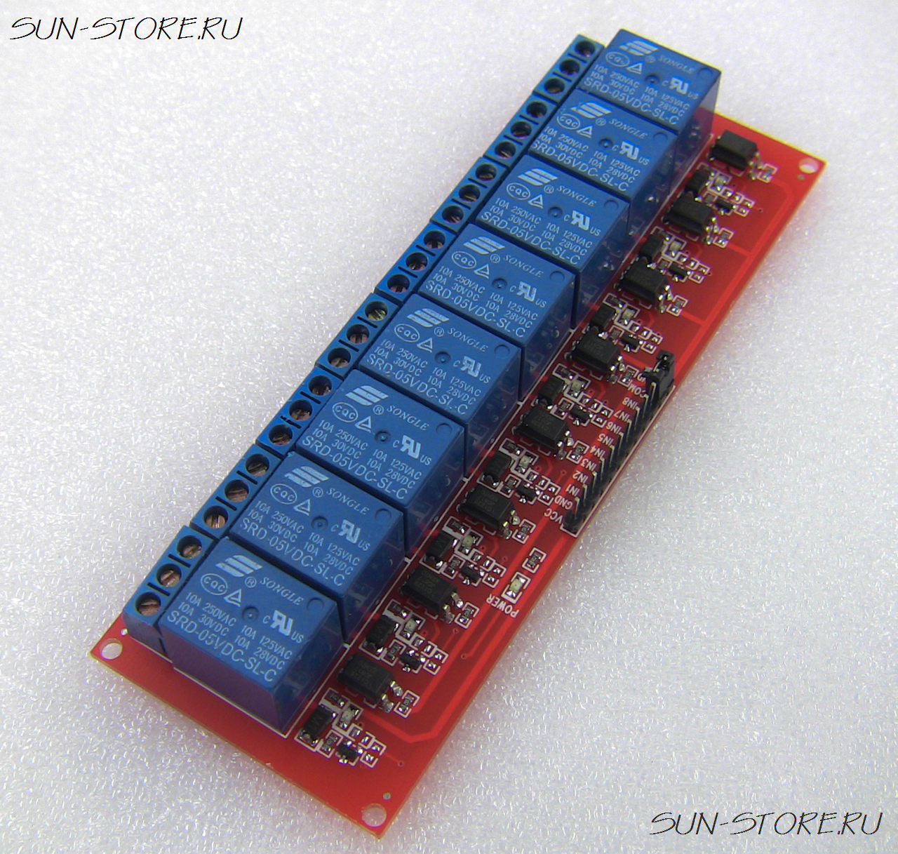
This is a 5V 4-Channel Relay interface board, Be able to control various appliances, and other equipments with large current. It can be controlled directly by Micro-controller (Arduino , 8051, AVR, PIC, DSP, ARM, ARM, MSP430, TTL logic) .
Features:
5V 4-Channel Relay interface board, and each one needs 15-20mA Driver Current
Equiped with high-current relay, AC250V 10A ; DC30V 10A
Standard interface that can be controlled directly by microcontroller (Arduino , 8051, AVR, PIC, DSP, ARM, ARM, MSP430, TTL logic)
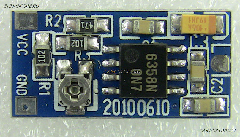
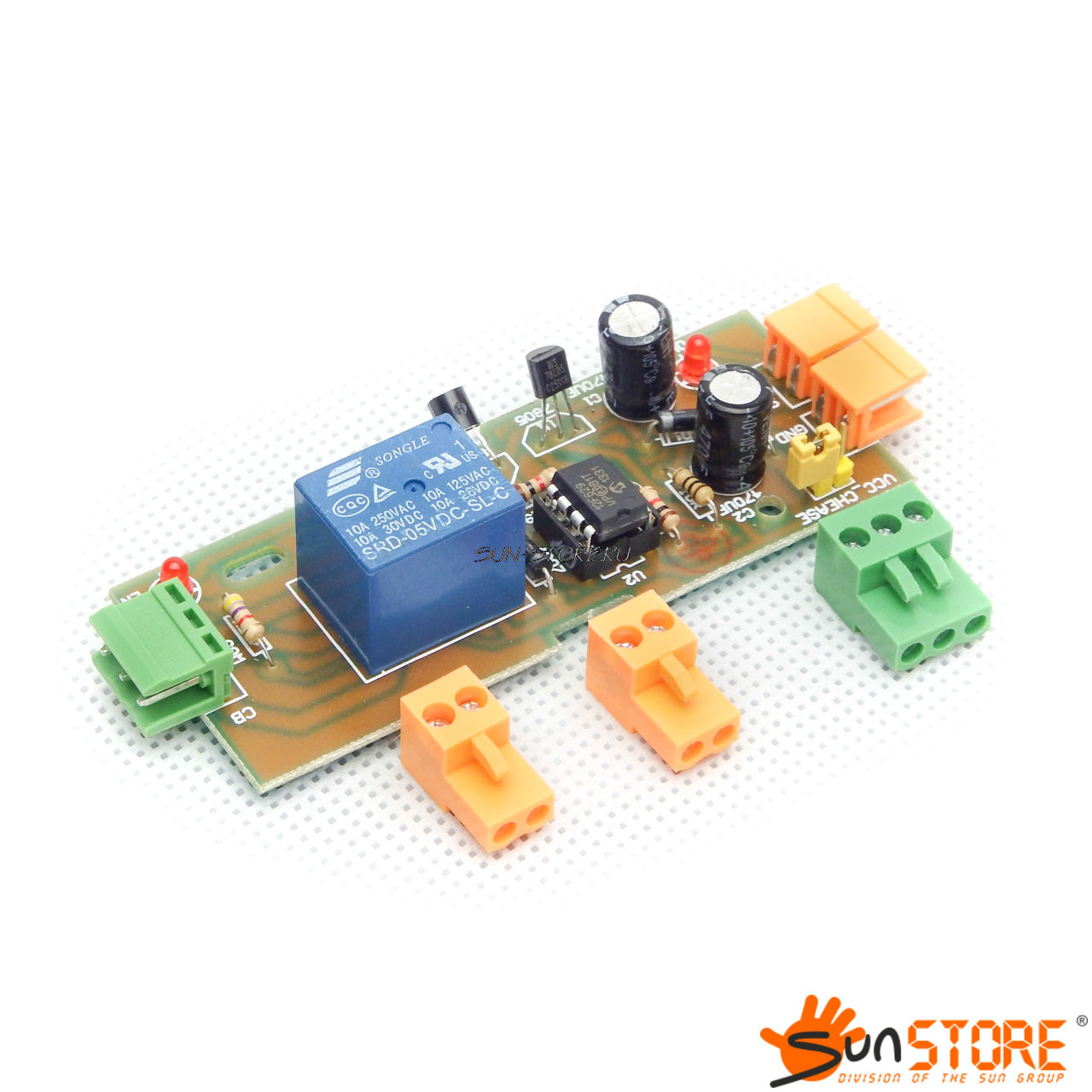
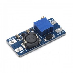
- 20- 500mA output current range (adjusted by pot on the board)
- 5-10V input
- TTL control (if required)
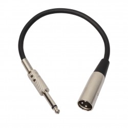
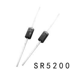
- Ideal for laser modules (for battery powered hosts this driver requires the diode to be electrically isolated if the diode if the diode is case+ve)
Compact, production quality board. This is a low drop out voltage linear current regulator. The Laser Diode +ve is connected to Power +ve and Laser Diode –ve is controlled by the circuit. (Note: for case +ve diodes the case cannot be grounded.) The minimum input voltage depends on the laser diode operating voltage and current setting, it is typically about 0.5 – 1.5 V higher than the laser operating voltage. Lower voltages will not allow the full current range and higher voltages will be dissipated by the driver as heat. (Max.~10V) The current required by the driver is typically 20-30mA higher than the output current. Stability is typically better than 3%. When the TTL +ve is not connected the output is a few mA, when it is powered above 2.5V the driver is enabled; it can be connected to power +ve for continuous operation. The TTL control can be used to switch the laser at rates up to 10kHz. Board color (the printed solder-resist layer) may be green or red depending on production batch.
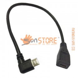
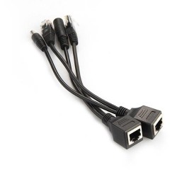
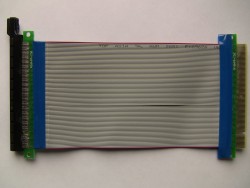
Когда-то я о таком модуле только мечтал, потом отметал мечты в сторону, разводил плату, травил, паял. Как же теперь все просто, а главное сколько времени экономится. Остается только соединить.
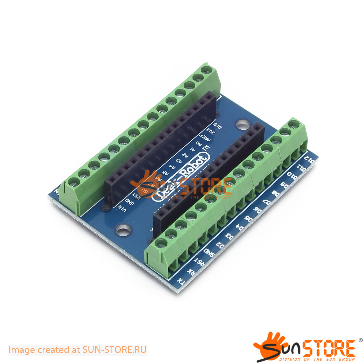
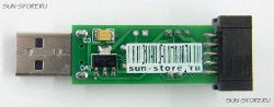
This is a terminal adapter for the Arduino Nano. It lables for Arduino Nano version 3.0, however you can still use this adapter for the older version (just have to remember that A0-A7 are in the reverse order). You can use this adapter to easily hook up Arduino Nano to an outside world via hook up wires.
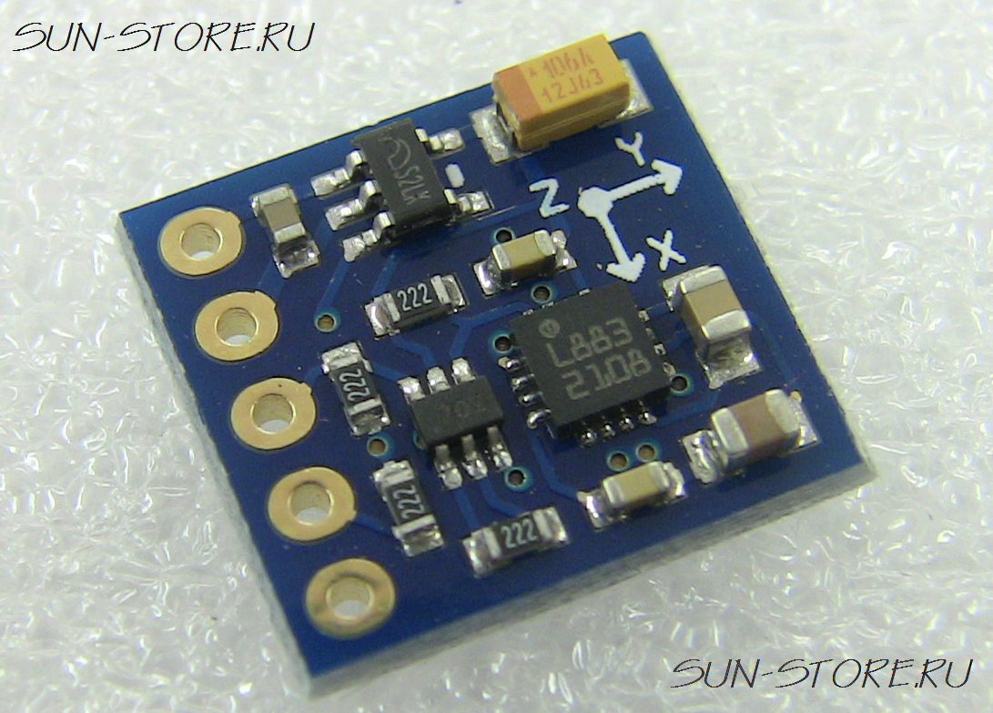
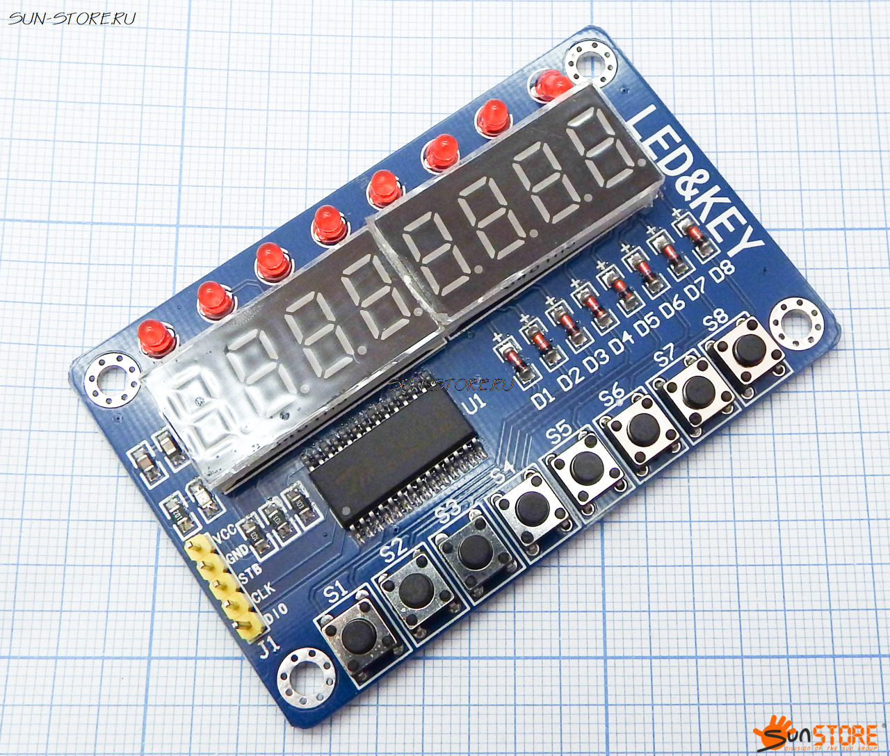
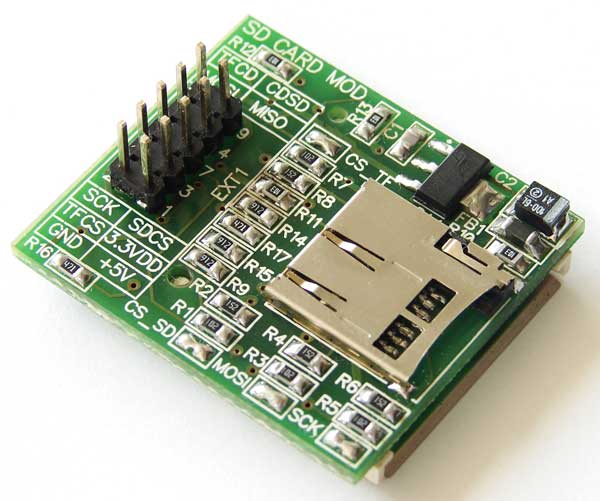
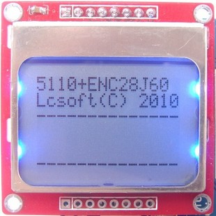
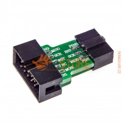
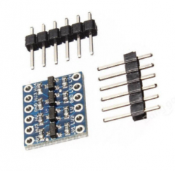
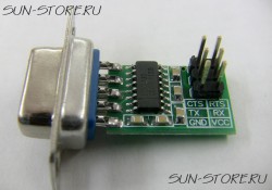
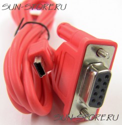
Cложного ничего, сериальный вход, но не SPI – линия данных на вывод и на ввод одна. Поэтому модуль рассчитан на подключение к произвольным пинам и обмен программный.
Видимо, для упрощения разводки платы получилось, что внутренняя память чередуется – байт – семисегментный индикатор, байт (мл. бит) – одиночный светодиод. Поэтому по времени вышло неоптимально – нельзя использовать автоинкремент адреса. Впрочем, при тех микросекундах, наверное, не имеет особого значения.
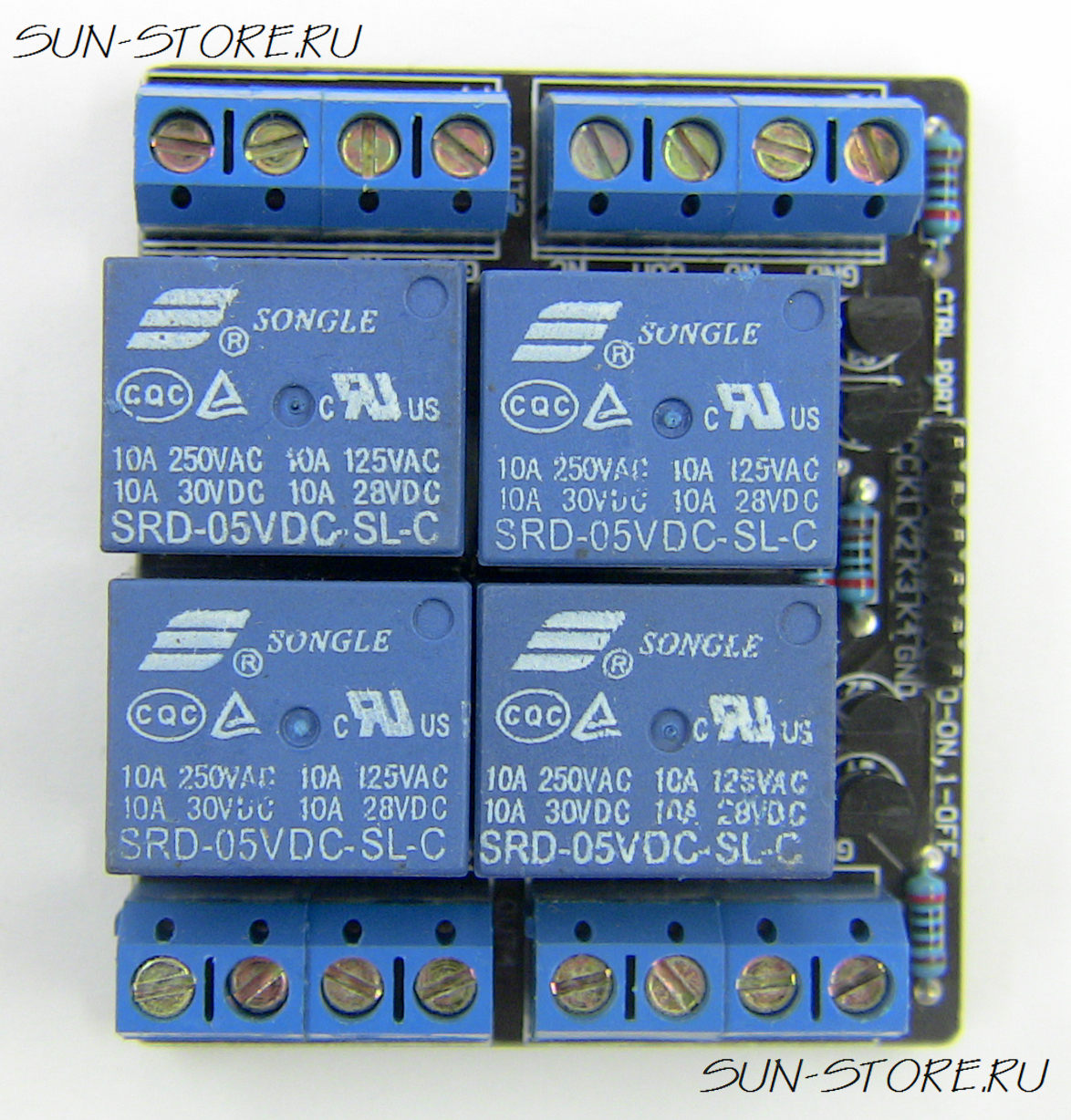
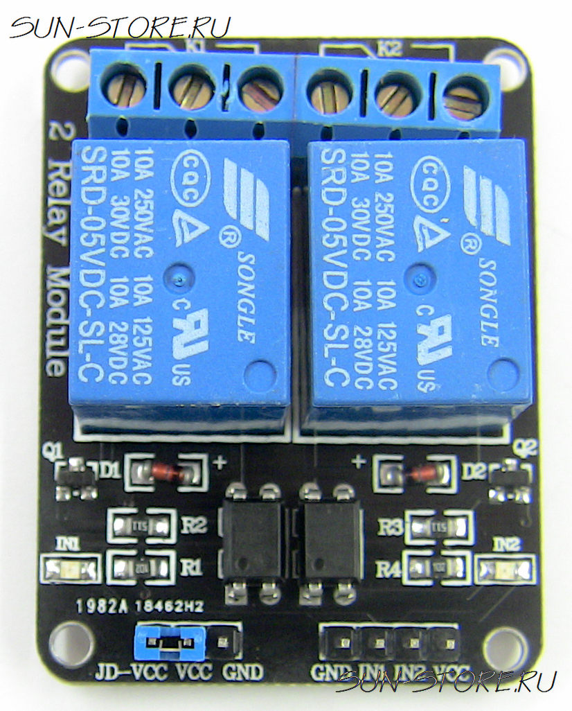
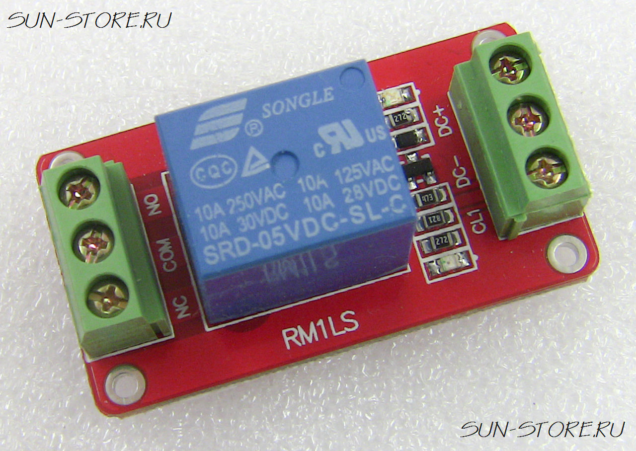
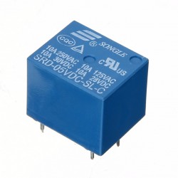
The module using genuine quality relay, normally open interface Maximum load: AC 250V/10A, DC 30V/10A;
Using high-power high-voltage transistor 2907A, driving ability, stable performance; trigger current of 5mA; Module operating voltage 5V, otherwise 12V and 24V modules to choose from;
Relay low level pull, the module containing the current limiting resistor, low level can GND, MCU I / O port is set low;
Fault-tolerant design, even if the control line is off, the relay will not operate;
Power indicator (red), 1 relay status indicator (blue)
Interface design user-friendly, all interfaces can connect directly leads to very convenient
Module size: 4.8cm * 2.6cm * 1.68cm (L * W * H)
There are four fixed bolt hole for easy installation.
Module interface
A module control end, 3-wire interface, all interfaces can connect directly leads to user-friendly
the VCC the external 5V
GND external GND
CL1 relay control interface, low level relay pull
B relay output, 3-wire interface, all interfaces can connect directly leads, user-friendly
NC relay normally closed interface, before the relay together with COM shorted pull vacant
COM relay public interface
NO relay normally open interface, the relay becomes vacant before the pull, pull shorted with COM.
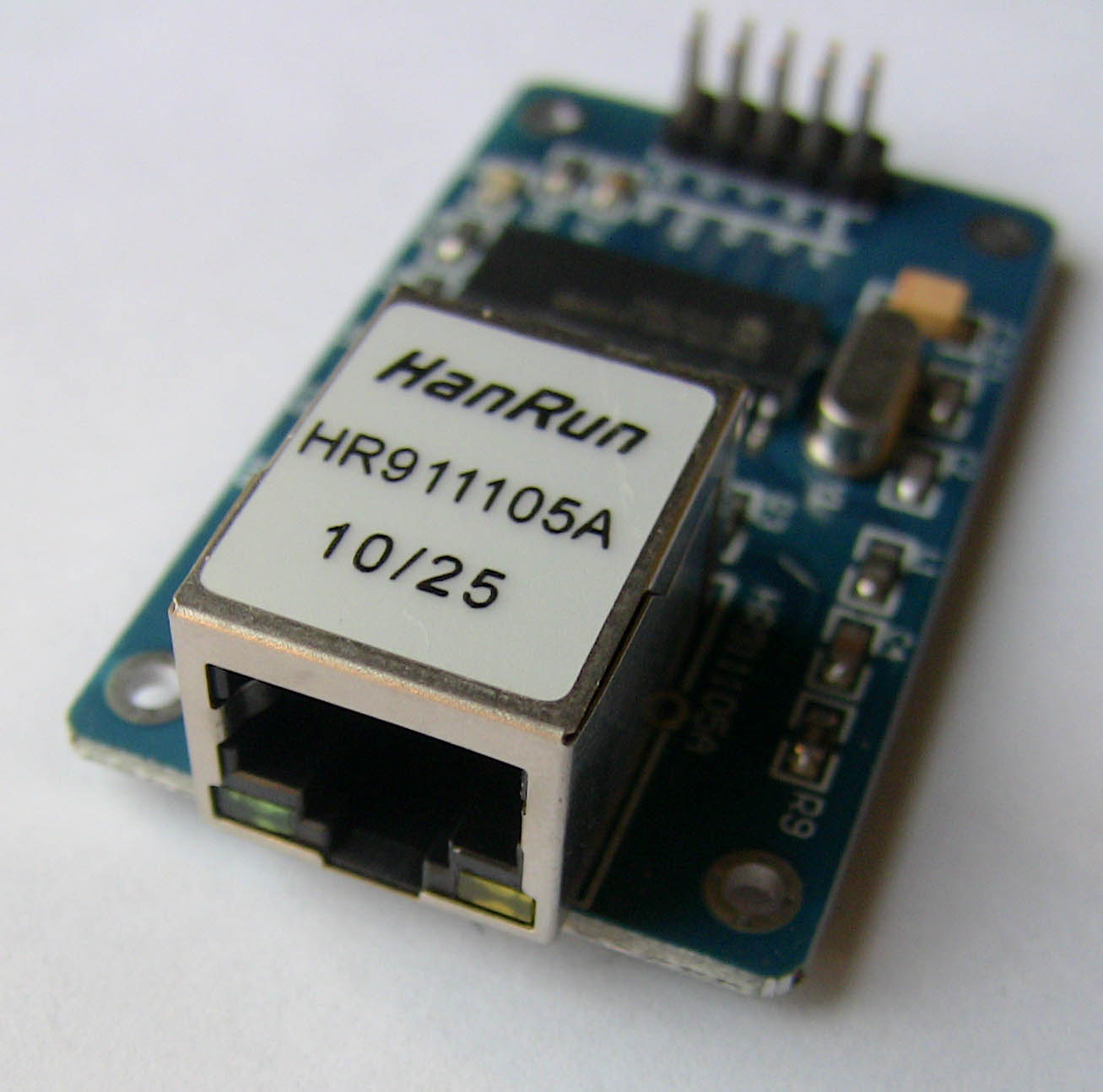
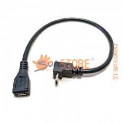
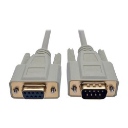
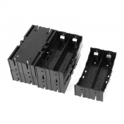
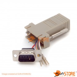
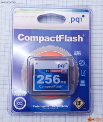
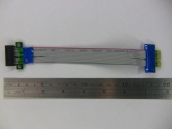
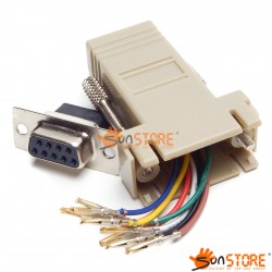
Очень часто перед разработчиком возникает задача подключить карту памяти к своему устройству или отладочной плате, и приходиться использовать навесной монтаж. В итоге конструкция превращается в переплетение проводов и резисторов, что совершенно не добавляет эстетичности получившемуся изделию, и снижает надежность в целом. Вариант с переразводкой печатной платы доступен далеко не каждому, к тому же он не всегда является целесообразным.
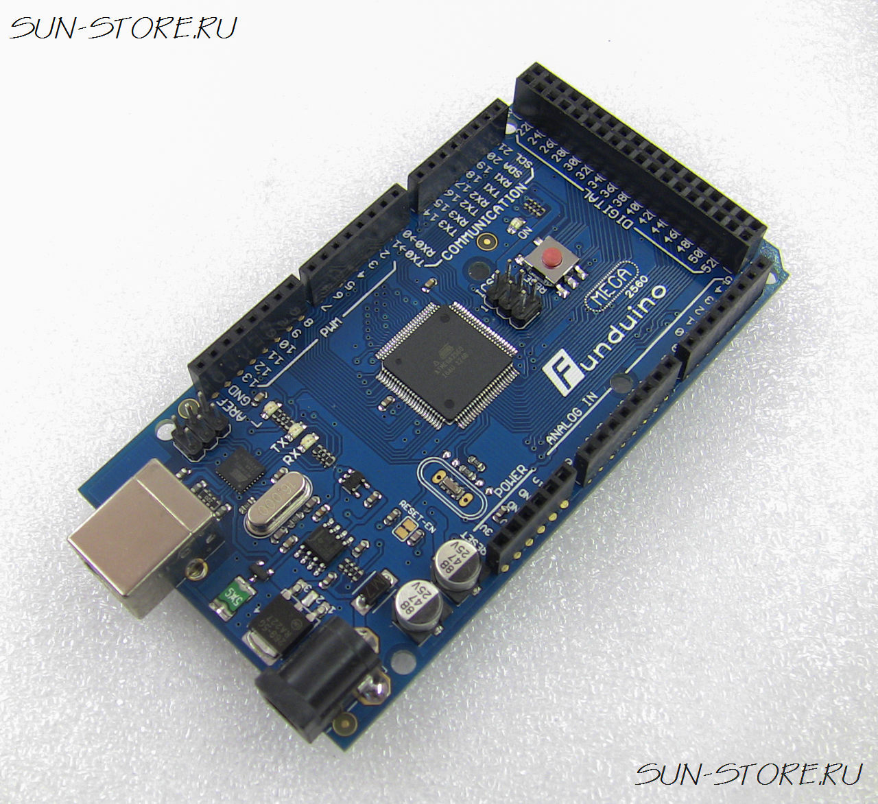
The Mega 2560 is a microcontroller board based on the ATmega2560 .It has 54 digital input/output pins (of which 14 can be used as PWM outputs), 16 analog inputs, 4 UARTs (hardware serial ports), a 16 MHz crystal oscillator, a USB connection, a power jack, an ICSP header, and a reset button. It contains everything needed to support the microcontroller; simply connect it to a computer with a USB cable or power it with a AC-to-DC adapter or battery to get started. The Mega is compatible with most shields designed for the Arduino Duemilanove or Diecimila.
The Mega 2560 is an update to the Arduino Mega, which it replaces.
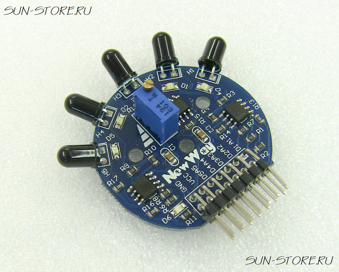
Using the five-channel flame sensor design, a wide detection range (Ordinary single flame sensor detection range is probably around 30 degree, as the distance increases, the range is gradually reduced, the detection range of the product is greater than 120 degree)
Able to output a digital signal (high and low), easy to use
Can output an analog signal (voltage signal), can be more accurate measurement of signal, for high precision occasions
Five outputs all have a status indicator which is convenient in debug and application
Digital output detection range is adjustable, analog output sensitivity adjustable with more flexible design
Uses 1% resistor design
A more accurate signal input, suitable for the needs of high-precision measurement occasions
On-board M3 mounting holes for easy installation; 3.3V~9V power supply, is compatible with most of the single-chip microcomputer system
SMD devices are used in all SMT process automatic soldering, military quality you can trust
Flame wavelength measurement range: 700~1100nm of short wave IR (SW-NIR), output via voltage signal.
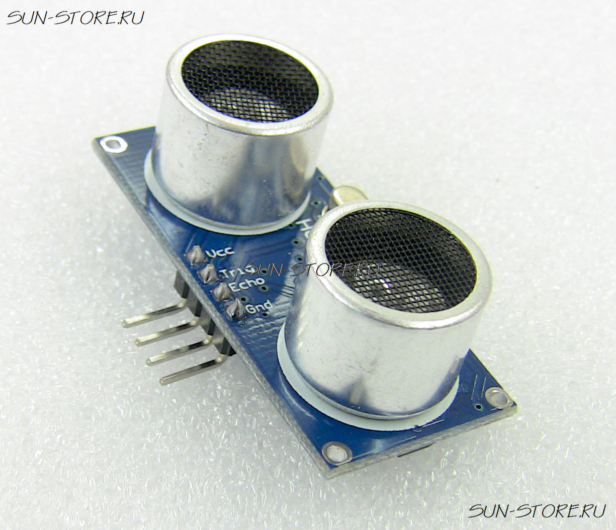
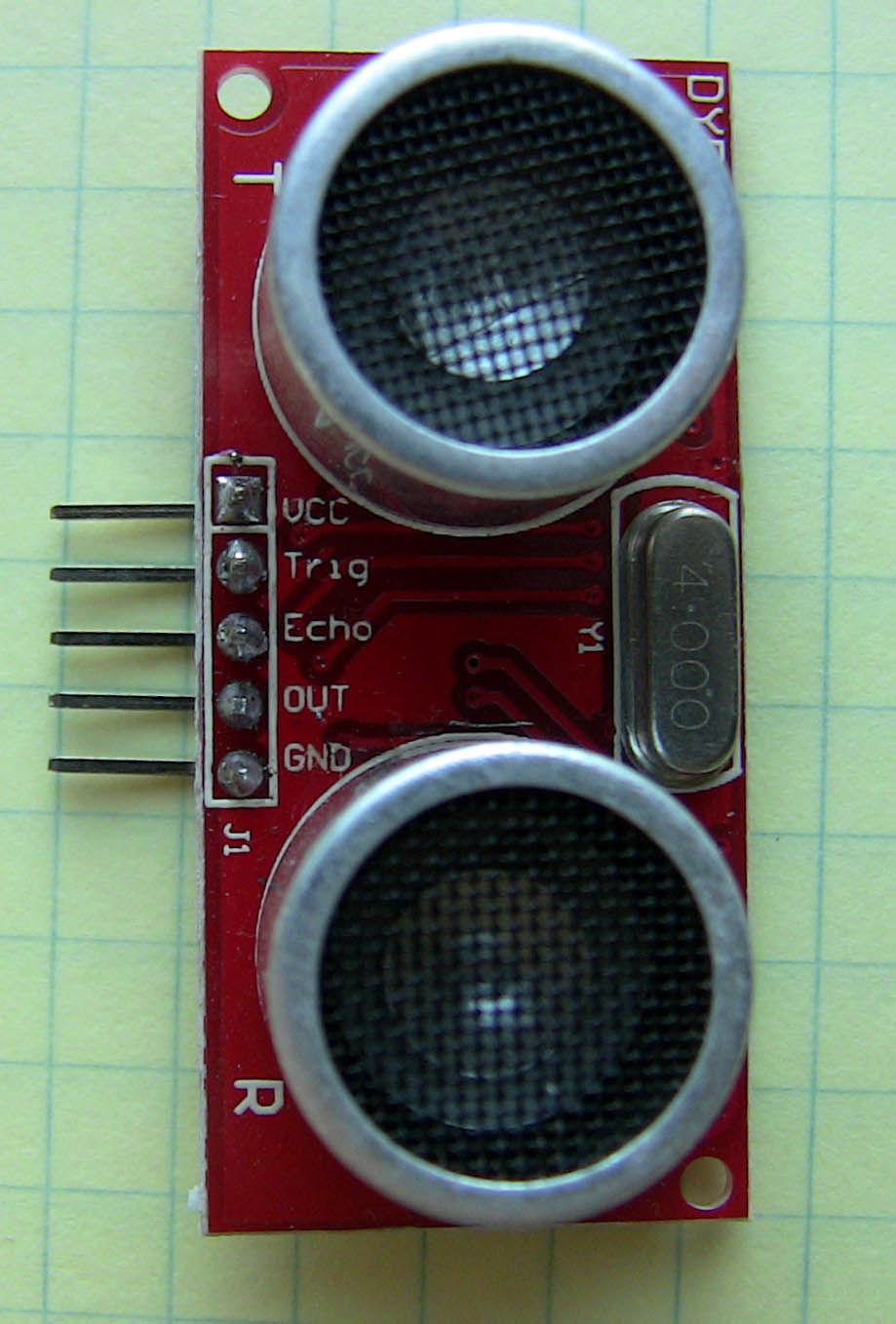
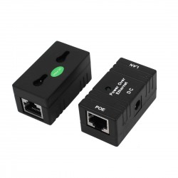
This US-020 ultrasonic module can realize 2 ~ 700cm of non-contact ranging function, has 5 V of wide voltage input range, static power consumption is less than 3mA. Their own temperature sensor will revise the ranging and has many communication modes like GPIO, just like watchdog inside, very stable and reliable.